Wind Turbine Controllers / Fast and Simulink
A tutorial on how to simulate Wind Turbine controllers using NREL's Fast and Matlab/Simulink
Project maintained by borgestassio Hosted on GitHub Pages — Theme by mattgraham
Instructions to set-up the environment to use Fast V8 and Matlab/Simulink:
Aiming in make the control design in the 5MW NREL wind turbine more fluid, this section will guide anyone interested in using the FAST V8 jointly with Simulink. This guide will cover simple, but essential, topics to make possible run simulations using the FAST V8 software from a Simulink model. In order to achieve that, we cover the following topics: 1 Compiling the S-Function from FAST V8 to your Matlab version; 2 Running the examples; 3 Read and plot output data; 4 Variable-Speed and Pitch controller through Simulink; 5 Comparison of DLL and Simulink results;
1 COMPILING THE S-FUNCTION
The Fast S-Function, called FAST_SFunc, is distributed with the FAST V8 software is compiled for the Matlab 2014b 32 bits version, in order to use this function in any other version, it need to be recompiled.
Note: If you use the Matlab 2014b 32 bits, you can go straight to topic 2
For re-compile the S-Function, you will need a MEX compiler. You can verify whether compiler is compatible with your Matlab version in this link: www.mathworks.com/support/sysreq/previous_releases.html
After installing the compiler, you need to configure the Matlab to identify your compiler. To do so you must enter the following command:
mex -setup
It will give you all compatible MEX compilers installed, if you have more than one, choose the one that suits you. If everything went fine, you are now able to compile your S-Function.
This procedure is quite simple: inside the folder “FastV8\Simulink\Source” you will find the file: “create_FAST_SFunc.m”. Open and run the file and, if no errors comes up, your re-compiled S-Function is ready for use.
2 RUNNING THE EXAMPLES
The FAST V8 comes with two example files to run with on Simulink, both are located inside the folder: “FastV8\Simulink\Samples” and each example has two files, a Matlab script file (.m) and a Simulink Model (.mdl). The script calls the mdl file and, when required, define the turbine parameters. As for the Simulink Model, it contains the S-Function called FAST_SFunc and blocks to insert the controllers for each controllable wind turbine component, we focus on the pitch controller on this repository (for now…)
We will start by the OpenLoop example, as this example will perform all certification tests provided by FAST V8 (1 – 26).
Note: If you use a 64 bits version of Matlab, your FAST_SFunc is also a 64 bits version, that means you need to change the _ServoDyn.dat file to call the 64 bits version of the DLL controller. To make this change, open the file “NRELOffshrBsline5MW_Onshore_ServoDyn.dat” inside the “…\Fast\CertTest\5MW_Baseline” folder and change the line 66 from *DISCON_win32.dll to ServoData/DISCON_x64.dll
As pointed by TheAfzalAmanullah: If you use a 64 bits version of Matlab, your FAST_SFunc is also a 64 bits version, that means you need to change the _ServoDyn.dat file to call the 64 bits version of the DLL controller. To make this change, open ALL the files that end in _ServoDyn.dat, for example “NRELOffshrBsline5MW_Onshore_ServoDyn.dat” inside the “…\Fast\CertTest\5MW_Baseline” folder and change the line 66 from DISCON_win32.dll to ServoData/DISCON_x64.dll
Assuming that you have sucesscefuly compiled the S_Func, you can run the file Run_OpenLoop.m to evaluate all certification tests with the FAST_SFunc, it may take a while to complete. If no error comes up, you will find new files in the CertTest folder, the output files from the SFunc have the extension: .SFunc.out or .SFunc.outb, if it is binary file format, we’ll get to that later.
Note: You can find the Run_OpenLoop.m commented on this folder, also the mdl file just in case.
Regarding the Test01_SIG example (also available on this folder), it consists of a replication of the certification test #1, but using a Simple Induction Generator inside the Simulink model (Test01_SIG.mdl) . Open the script file (Run_Test01_SIG.m) and you can see that some wind turbine parameters are defined in the file before calling the Simulink Model. We can see the Simple Induction Generator controller in the Simulink block, just double-click the Simple Induction Generator block and it will open the controller. Before running this example you must follow the instruction in the scrip file, which is to change the CertTest\AWT27\Test01_ServoDyn.dat file to set VSControl = 4.
3 READ AND PLOT DATA
Once all certification tests are done, you will be able to see some new files in the certification test, as stated above, these new files have the .SFunc.out or SFunc.outb extension, and contain the data from the simulation using the SFunction.
One way to manipulate the data is to import the file through Matlab where you can easily plot a graph. However, as we are already using the FAST functions, why not use their tools? They have a function called ReadFASTbinary, located in the folder “Utilities\MATLAB_Toolbox\Utilities”. This function only needs an input parameter, which is the file name. You can use the following command as an example:
ReadFASTbinary('Test18.outb')
It will create two new variables, OutData and OutList, where the first contains all numeric data from the simulation, and the second contains the names of the parameters of each column inside OutData.
If you want to plot the data, there is also a function to do so, just call the PlotFASToutput function to plot all the data from your simulation, one variable for each figure. You can enter the following command as an example:
PlotFASToutput({'Test18.out'})
Note: The input to the PlotFASTouput function is a cell containing all files you want to plot, this is done to ease the comparison between simulation, as you can simply input two files to this function and they will be plotted in the same figure.
Alternatively, you can use anyother method to plot the data.
4 VARIABLE-SPEED AND PITCH CONTROLLER THROUGH SIMULINK
This guide focus on developing controllers for the 5MW NREL wind turbine, and as a start point, we choose the certification test #18 (Test18.fst) to perform the initial tests, mainly because the controllers used in this certification tests are implemented by the DISCON.f90 source file and can be used for comparison. The objective of this section is to copy the controller from the DLL interface, written in the DISCON.f90 file, to the Simulink and obtain the results. All the files used are present on the appropriate folder and you can modify them to achieve your goals. The only limit are the functions available on Simulink itself, as we’ll see later.
In the figures below show an overview of the Simulink Model, the implementation of the Pitch Controller and the Torque Controller as outlined in the baseline controller. I won’t get into details about the Torque Controller, but we’ll go through the PID controller for the pitch angle as it’ll be our point of comparison when implementing the other controllers.
4 COMPARISON OF DLL AND SIMULINK RESULTS
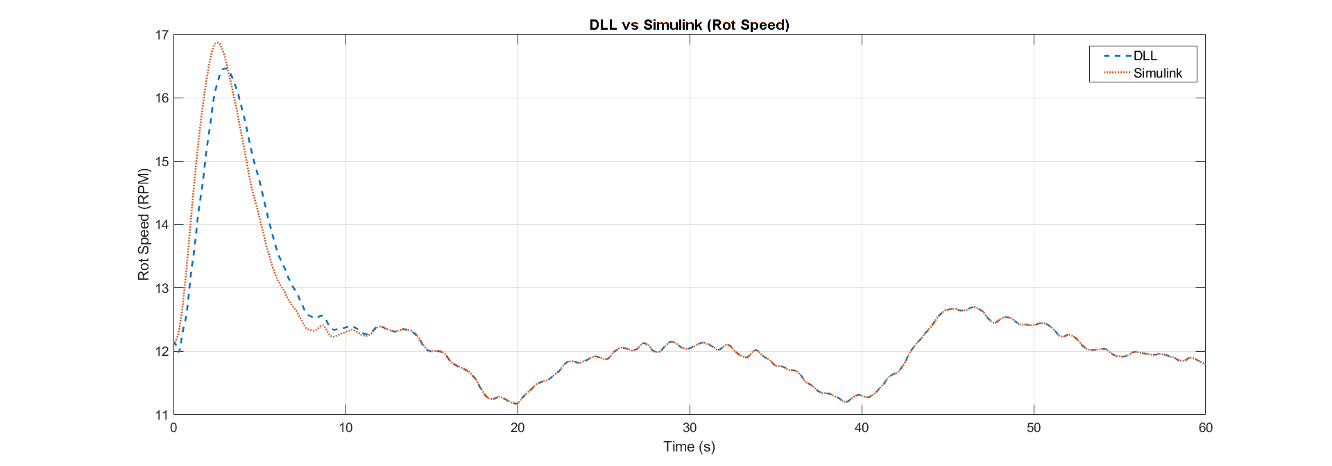
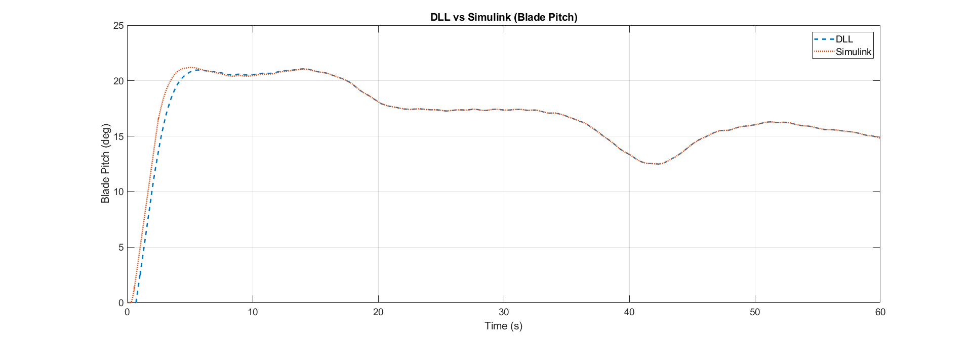
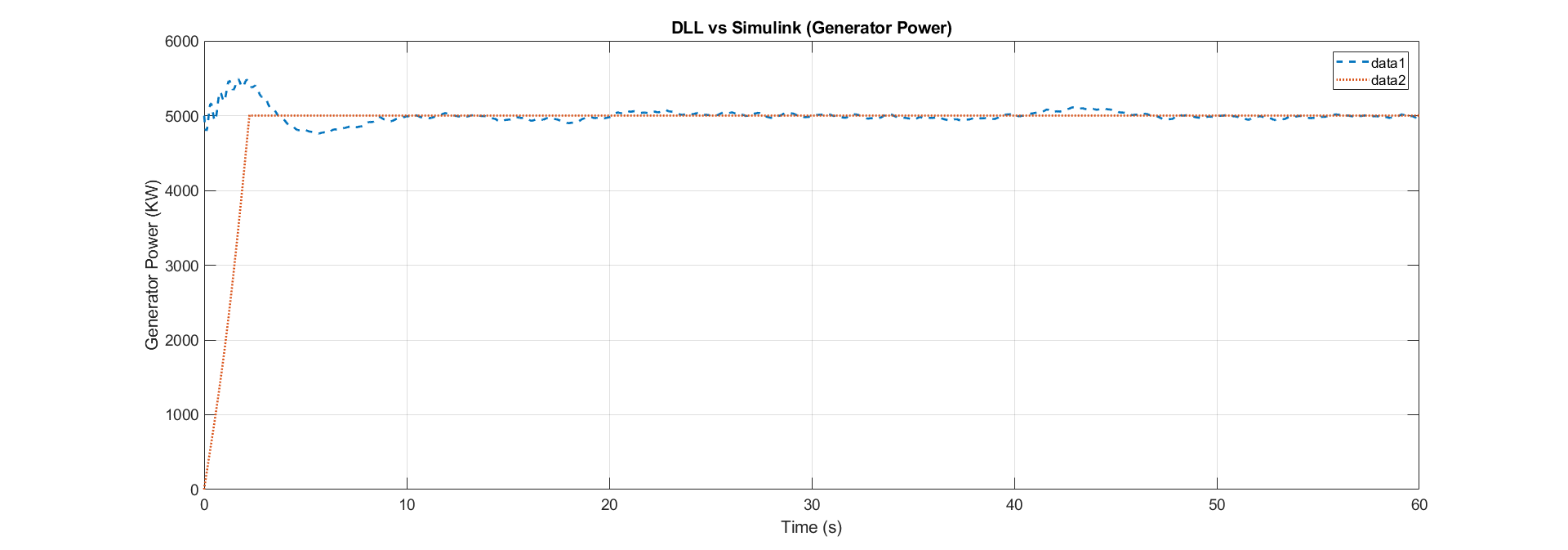
To compare the results we simply run the Test18.fst with no changes first, then we change the NRELOffshrBsline5MW_Onshore_ServoDyn.dat The results we are interested in are Rotor Speed, Pitch and Power, are respectively compared in the graphs below. The differences clearly noted are discussed on the NREL Forum, and are probably due to the initial values on the Simulink, which are usually 0, this is easily noted on the generator graph. Despite these differences, when a longer simulation is executed, the values tend to be the equal and the during the analysis we might discard the initial data.


Note: We’ll go into details about the data indexing and filtering when implementing the controllers
If you want to learn a bit more visit the State Space Feedback section.